Power phases
The number of processor power phases provided on the motherboard.
Very simplistically, phases can be described as electronic blocks of a special design, through which power is supplied to the processor. The task of such blocks is to optimize this power, in particular, to minimize power surges when the load on the processor changes. In general, the more phases, the lower the load on each of them, the more stable the power supply and the more durable the electronics of the board. And the more powerful the CPU and the more cores it has, the more phases it needs; this number increases even more if the processor is planned to be overclocked. For example, for a conventional quad-core chip, only four phases are often enough, and for an overclocked one, at least eight may be needed. It is because of this that powerful processors can have problems when used on inexpensive low-phase motherboards.
Detailed recommendations on choosing the number of phases for specific CPU series and models can be found in special sources (including the documentation for CPU itself). Here we note that with numerous phases on the motherboard (more than 8), some of them can be virtual. To do this, real electronic blocks are supplemented with doublers or even triplers, which, formally, increases the number of phases: for example, 12 claimed phases can represent 6 physical blocks with doublers. However, virtual phases are much inferior to real ones in terms of capabilities — in fact, t...hey are just additions that slightly improve the characteristics of real phases. So, let's say, in our example, it is more correct to speak not about twelve, but only about six (though improved) phases. These nuances must be specified when choosing a motherboard.
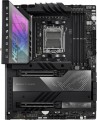
Metal backplate
The presence
of a metal backplate in the design of the motherboard.
The backplate is a special plate located on the back side of the board (that is, on the opposite side from the connection slots). This feature is typical mainly for advanced "motherboards" designed for powerful systems: individual components of such systems (especially cooling) can be very heavy, and installing them directly on the board would be fraught with damage to it. And the metal backplate avoids this: it plays the role of an additional support that removes the main load from the motherboard. At the same time, such a plate is usually made thick and elastic enough to transfer even a very significant weight of components without consequences.
Chipset
The chipset model installed in the motherboard. AMD's current chipset models are
B450,
A520,
B550,
X570,
A620,
B650,
B650E,
X670,
X670E,
B840,
B850,
X870,
X870E. For Intel, in turn, the list of chipsets looks like this:
X299,
H410,
B460,
H470,
Z490,
H510,
B560,
H570,
Z590,
H610,
B660,
H670,
Z690,
B760,
Z790,
H810,
B860,
Z890.
A chipset is a set of chips on the motherboard through which the individual components of the system inter
...act directly: the processor, RAM, drives, audio and video adapters, network controllers, etc. Technically, such a set consists of two parts — the north and south bridges. The key element is the northbridge, it connects the processor, memory, graphics card and the southbridge (together with the devices it controls). Therefore, it is often the name of the north bridge that is indicated as the chipset model, and the south bridge model is specified separately (see below); it is this scheme that is used in traditional layout motherboards, where bridges are made in the form of separate microcircuits. There are also solutions where both bridges are combined in one chip; for them, the name of the entire chipset can be indicated.
Anyway, knowing the chipset model, you can find various additional data on it — from general reviews to special instructions. An ordinary user, usually, does not need such information, but it can be useful for various professional tasks.Max. clock frequency
The maximum RAM clock speed supported by the motherboard. The actual clock frequency of the installed RAM modules should not exceed this indicator — otherwise, malfunctions are possible, and the capabilities of the “RAM” cannot be used to the fullest.
For modern PCs, a RAM frequency of
1500 – 2000 MHz or
less is considered very low,
2000 – 2500 MHz is modest,
2500 – 3000 MHz is average,
3000 – 3500 MHz is above average, and the most advanced boards can support frequencies of
3500 – 4000 MHz and even
more than 4000 MHz.
SATA 3 (6Gbps)
Number of
SATA 3 ports on the motherboard.
SATA is now the standard interface for connecting internal drives (mainly HDDs) and optical drives. One device is connected to one such connector, so the number of SATA ports corresponds to the number of internal drives / drives that can be connected to the motherboard through such an interface. A large number (
6 SATA ports and more) is necessary in case of active use of several hard drives and other peripherals. For domestic use, 4 is enough. SATA 3, as the name suggests, is the third version of this interface, operating at a total speed of about 6 Gbps; the useful speed, taking into account the redundancy of the transmitted data, is about 4.8 Mbps (600 MB / s) — that is, twice as much as in SATA 2.
Note that different SATA standards are quite compatible with each other in both directions: older drives can be connected to newer ports, and vice versa. The only thing is that the data transfer rate will be limited by the capabilities of the slower version, and in some cases it may be necessary to reconfigure the drives with hardware (switches, jumpers) or software. It is also worth saying that SATA 3 is the newest and most advanced variation of SATA today, but the capabilities of this standard are not enough to unlock the full potential of high-speed SSDs. Therefore, SATA 3 is mainly used for hard drives and low-cost SSDs, faster drives are conn
...ected to specially designed connectors like M.2 or U.2 (see below).M.2 version
The version of the M.2 interface determines both the maximum data transfer rate and the supported devices that can be connected via physical M.2 connectors (see the corresponding paragraph).
The version of the M.2 interface in the specifications of motherboards is usually indicated by the number of connectors themselves and by the PCI-E revision provided for in each of them. For example, the entry “3x4.0” means three connectors capable of supporting PCI-E 4.0; and the designation “2x5.0, 1x4.0” means a trio of connectors, two of which support PCI-E 4.0, and another one supports PCI-E 5.0.
SAS connector
The number of SAS ports on the motherboard.
SAS is a modification of the SCSI interface and is usually used to connect drives. Devices with this interface are mainly used in server systems and are practically not found in ordinary desktop PCs. The data transfer rate reaches 6 Gbps (750 Mb/s). It is worth noting that SATA2 and SATA3 drives (see the relevant glossary entries) can be connected to the SAS interface; at the same time, a SAS device cannot be connected to the SATA interface.
1x PCI-E slots
Number of PCI-E (PCI-Express) 1x slots installed on the motherboard. There are
motherboards for 1 PCI-E 1x slot,
2 PCI-E 1x slots,
3 PCI-E 1x ports and even more.
The PCI Express bus is used to connect various expansion cards — network and sound cards, video adapters, TV tuners and even SSD drives. The number in the name indicates the number of PCI-E lines (data transfer channels) supported by this slot; the more lines, the higher the throughput. Accordingly, PCI-E 1x is the basic, slowest version of this interface. The data transfer rate for such slots depends on the PCI-E version (see "PCI Express Support"): in particular, it is slightly less than 1 GB / s for version 3.0 and slightly less than 2 GB / s for 4.0.
Separately, we note that the general rule for PCI-E is as follows: the board must be connected to a slot with the same or more lines. Thus, only single-lane boards will be guaranteed to be compatible with PCI-E 1x.
USB 2.0
The number of USB 2.0 connectors provided on the motherboard.
USB connectors (all versions) are used to connect to the "motherboard" USB ports located on the front panel of the case. With a special cable, such a port is connected to the connector, while one connector, usually, works with only one port. In other words, the number of connectors on the motherboard corresponds to the maximum number of front USB connectors that can be used with it.
Specifically, USB 2.0 is the oldest version widely used nowadays. It provides data transfer rates up to 480 Mbps, is considered obsolete and is gradually being replaced by more advanced standards, primarily USB 3.2 gen1 (formerly USB 3.0). Nevertheless, a lot of peripherals are still being produced under the USB 2.0 connector: the capabilities of this interface are quite enough for most devices that do not require a high connection speed.